
Total indicator runout, or TIR, is a term often used in manufacturing, especially when dealing with rotating parts. Other names include total indicator reading, or more recently, full indicator movement (FIM). TIR is simply the difference between the maximum and minimum values measured across an entire rotating surface about a reference axis.
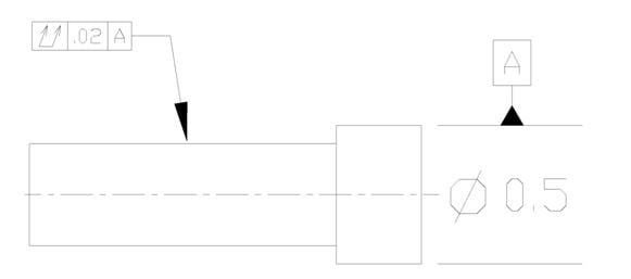
When called out on a blueprint, TIR creates a boundary zone in which all points on the specified surface must fall between in order for the part to meet spec. The symbol used is a connected double arrow along with a value referenced against a datum axis. See below for a graphical representation:

This representation is stating that given datum axis A, all the points on the smaller shaft surface must fall within .02” when rotated 360°. In order to check this, TIR is often measured using a dial indicator, or several in conjunction with each other, and a set of v-blocks.
WHAT IS RUNOUT?
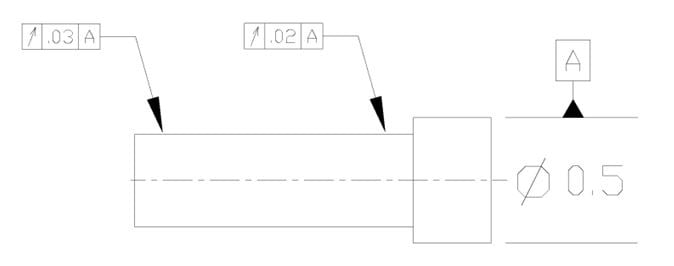
Runout is similar in concept to TIR but applies only to a specified location or locations, and not the entire rotating surface. The minimum or maximum value at each location is treated independently of all other locations. The symbol used is a single arrow along with a value referenced against a datum axis. See below:


This representation is stating that given datum axis A, all points of the individual cross-section of the smaller shaft closest to the larger hub must fall within .02” when rotated 360°. All points of the individual cross-section of the smaller shaft furthest from the larger hub must fall within .03” when rotated 360°. Runout is often measured using a dial indicator and a set of v-blocks.
WHY ARE TIR AND RUNOUT IMPORTANT?
If the central axes of the two parts above were offset directionally, angularly, or a combination of both this could lead to excessive stresses on the parts, premature wear, and potential failure of the parts or system. Specifying TIR or runout establishes the boundary by which the parts will properly function for their designed use and life cycle.
By the very nature of Rotary friction welding these terms come into play. One part is chucked in a spindle and rotated at high speed while the other part is held stationary and pressed against the rotating part. The friction between the two pieces creates heat and the axial load force forges the two pieces together.
While the friction welding process does not improve upon incoming part tolerances, great care is taken to ensure that both parts are correctly aligned relative to one another. Due to the weld torques involved with friction welding, there may be machine and/or part deflections that can affect the alignment between the two parts. With proper development and tooling design, however, it is possible to achieve finished tolerances similar to that of machining with the friction welding process.
FIND YOUR SOLUTION
Since 1976 MTI has specialized in providing solid-state joining and welding solutions, equipment, and services. Our experience spans a number of industries including agricultural, construction, aerospace, defense, marine, and automotive. We’re prepared to find a solution for your needs. We’ll build a machine that makes your part, we’ll make the part for you, or we’ll help you make the part even better.
To learn more about friction welding, visit our website or watch how friction welding can be put to work for you.
